IOL The maximum output current corresponding to logic 0 state. IOH The minimum output current corresponding to logic 1 state. IIL The maximum input current corresponding to logic 0 state. IIH The minimum input current correspondingg to logic 1 state.

VIH = 2 V, VOH = 2.4 V, VIL = 0.8 V and VOL = 0.4 V VOL The maximum output voltage coresponding to logic 0 state. VOH The minmum output voltage corresponding to logic 1 state. VIL The maximum input voltage to be recognized as logic 0 state. VIH The minimum input voltage to be recognized as logic 1 state. for a standard TTL, power dissipation 19 mW. It signifies the wastage of power in a digital circuit. If tPHL = 14 ns and tPHL = 20 ns, then tp = 14 + 20 /2 = 17 ns. for a standard TTL, the propagation delay time is 18.5 ns. The speed of operation of a TTL is specified in terms of propagation delay time. The logic symbols for the active high and actice low enable input inverters are shown in fig. The tri-state inverter has two inputs normal input A and enable input E. The circuit of a tri-state TTL inverter is shown in figure. when the output is in high-impedance state, it acts as open or floating and there is no sink and source current as shown in fig. when the output is high, the driver gate supplies the current to the load as shown in fig. When the output is low the driver gate sinks the load current as shown in fig. in high-impedance state, both T3 and T4 in totem-pole arrangement are tured off and as a result the output is open or floating. In TTL with totem-pole output T3 is on when the output is low and T4 is on when the output is high. the tri-state TTL has three output states, high low and high-impedance. if the output is not in low state, it should definitely in the high state. the output is either in high state or low state. figure shows the circuit of a TTL NAND gate with open collector output.Ī normal digital circuit has two output states, low and high. this problem of TTL with totem-pole output is overcome in TTL with open collector output. TTL with totem-pole output has a major problem that the two outputs of the two gates cannot be connected together. Here, the outputs of two NAND gates are connected together. using a wired-AND connection, the fan-in of the circuit is increased. In terms of 0 and 1, table (a) can be written as in table (b).Ī wired-AND connection has two or more than two gates connected together. The operation of the circuit is summarized in table (a) TTL with active pull-up is known as TTL with totem-pole output.


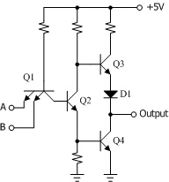
What is ttl circuit with totem-pole output stage minimize gate and advantages disadvantages or ttl with totem pole output ?įigure shows the circuit of a two-input TTL NAND gate with totem-pole output.


 0 kommentar(er)
